Designing sheet metal parts looks easy in CAD—until you send it to the shop and get back a warped bracket, holes too close to a bend, or a stiffener that requires a $100k press.
This guide breaks down the essentials of sheet metal DFM: bend reliefs, K-factors, hole spacing, stiffening techniques, and the little gotchas that separate a smooth build from a pile of scrap. Think of it as the “don’t learn the hard way” manual for anyone who touches sheet metal.
Preview: Introduction
Sheet metal is one of the most versatile manufacturing processes. It begins with flat sheets of metal, known as “blanks” and serve as the raw material to be transformed into functional parts through different shaping techniques. The blank can be stamped into complex forms, bent to create flanges, cut into specific shapes, or punched to create holes or slots.The advantage is precision: you can create complex shapes without much material waste.
Manufacturing Volume: Highly cost-effective across different production volumes. Setup involves minimal tooling requirements and fast cycle times.
Applications: automotive, aerospace, electronic enclosures, appliances, etc.
Considerations: Quick, repeatable, and scalable, but design needs to account for its limits—uniform thickness, minimum bend radii, and a susceptibility to warping.

Common Forming Processes
Sheet metal fabrication transforms flat sheet metal into components with a desired shape and size. This is achieved using common processes like the following:
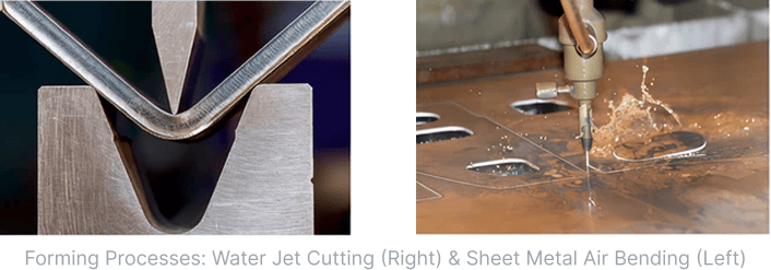
Bending: Forms sheet metal into various angles using press brakes or other bending equipment. Critical to account for bend radius, spring-back, and material grain direction.
Cutting Techniques😀
Laser Cutting: Uses a high-powered laser to cut complex shapes with tight tolerances. Ideal for thin to medium-thickness sheets with intricate designs.
Water Jet Cutting: High-pressure water with abrasive particles cuts thicker materials without heat-affected zones.
Punching: Utilizes a punch and die to create holes, slots, and other features in sheet metal.
Stamping: Shapes sheet metal through a press with dies, often used for high-volume production of complex parts. Includes sub-processes like deep drawing, coining, and embossing.
Forming: Operations like roll forming, where metal sheets are continuously shaped through a series of rolls, and hydroforming, which uses high-pressure fluid to form sheets into complex shapes.

Sheet metal bending is where a flat sheet is formed into a desired shape by applying force along a specific axis.
Used to create parts with angles, flanges, and curves, forming everything from enclosures to brackets.
Bending involves complex material behavior—stretching in tension on the outside and compression on the inside of the bend—all of which impact final dimensions.
Key Considerations in Bending
Bend Allowance (BA): The amount of material needed to accommodate stretching along the neutral axis during bending.
Bend Deduction (BD): Length of material necessary to remove from the total length of the plate to obtain the correct flat pattern dimensions.
After bending, the flange length (i.e., the total length) is greater than the length of the sheet metal flat pattern.
Compensates for the material’s spring back effect, where bent part unbends after bending force removed.

When to Use:
If you know the size of your flat material and want to calculate how long the flanges will be after bending, bend allowance is what you want.
If you know what size flanges you want to end up with after bending and need to calculate the size of the flat pattern to start with, bend deduction is what you want.

Step 1: Define the Functional Requirement
K-factor: measures how the neutral axis shifts inward as the material thins during bending…
5 minute engineering drawings with Drafter
We’re building a tool that lets you go from 3D model to manufacturing-ready 2D drawing in minutes—not hours. No more clicking through a hundred dropdowns or babysitting your title block. Just fast, clean drawings with proper GD&T, ready to send to the shop.
Whether you’re designing aerospace components or bike parts, Drafter gets you to a drawing faster than your coffee gets cold.
We’re already working with teams in aerospace, robotics, automotive, medical devices, and energy—basically anywhere engineers are tired of wasting time on the boring stuff.
We'd love your feedback! If there are specific resources or tools you'd like Drafter to create, please reach out anytime. Your input directly shapes the tools we build.
Happy engineering,
The Drafter Team
